Feb 14, 2008

MPLS VPNs

MPLS VPNs are connectionless. MPLS seperates traffic and provides privacy without the need for Layer 2 tunneling protocols and encryption. This eliminates significant complexity during the provisioning process.

MPLS solves the scalability issues encountered by Frame Relay and ATM deployments by allowing service providers to provision multiple VPNs for multiple customers without the chore of provisioning tens to hundreds of virtual circuits for each and every closed user group or customer. An example of an MPLS VPN is shown in the picture below. Customers A and B share the service provider infrastructure while having the ability to form their own closed user groups with utmost security. They also can run their own routing protocols.


The MPLS model requires the CPE routers to directly exchange routing information with provider edge routers, as opposed to exchanging routing information with all other CPE routers that are members of the VPN. Members of the VPN are identified as belonging to the closed user group by means of labels. These labels carry next-hop information, service attributes, and a VPN identifier, which keeps communications within a VPN private.

At the ingress into the provider network, incoming packets from the CPE router are processed, and labels are assigned based on the physical interface these packets were received from. Labels are applied using VRF (VPN Routing and Forwarding) tables. The forwarding tables are predetermined, and incoming packets are examined only at the ingress LSR. The core devices or Provider (P) LSRs merely forward these packets based on labels.

Reference :
“Advanced MPLS Design and Implementation”, Vivek Alwayn, Cisco Press, 2002.


Feb 13, 2008

IP Virtual Private Networks (IP VPNs)

Many carriers provide a managed IP services offering that basically lets customers hook up their CPE IP routers to a service provider’s private IP backbone. Most IP Service providers run an IP network over a Layer 2 infrastructure such as an ATM or Frame Relay network. An example of a conventional IP VPN is shown in the picture below.


The service provider typically configures multiple routing protocols or runs multiple routing processes on its backbone routers for various customers. Typically, the Cisco Routing engine supports the operation of multiple routing protocols in a single router in order to connect networks that use different routing protocols. The routing protocols available are inherently designed to operate independently of each other. Each protocol collects different types of information and reacts to topology changes in its own way. For example, RIP uses a hop count metric and EIGRP uses a five-element vector of metric information.

Customers perceive a private IP VPN by virtue of a combination of access lists, routing protocols, and processes.

The biggest issue facing managed IP service providers is scalability and complexity of implementation. The number of available routing protocols and routing processes supported per router platform sometimes forces service providers to deploy separate routers for each customer VPN at the service provider’s point of presence.

Reference :
“Advanced MPLS Design and Implementation”, Vivek Alwayn, Cisco Press, 2002.


Asynchronous Transfer Mode and its Virtual Connections

Asynchronous Transfer Mode (ATM) is derived from standards developed by the ITU-T that were based on BISDN (Broadband ISDN) technology.

ATM is a connection-oriented service in which transmitted data is organized into fixed-length cells. Upper-layer protocols and user data such as an IP packet are segmented into 48-byte protocol data units (PDUs). These PDUs are prepended with a 5-byte ATM header, and the resulting 53-byte cells are input into an ATM switch and multiplexed together. These cells then contend for vacant slots in the outgoing ATM cellstream.

Each ATM cell header contains a virtual path identifier (VPI) and a virtual channel identifier (VCI), which together define the ATM virtual circuit the cell needs to follow on its path toward its destination. The arrival rate, or delay, of one particular cell stream is not periodic. Therefore, the cell transfer is referred to as Asynchronous Transfer Mode, in contrast to synchronous transfer, such as TDM transport, which uses fixed time periods for frame transmission and reception.

Each ATM cell contains information that identifies the virtual connection to which it belongs. That identification has two parts : a virtual channel identifier and a virtual path identifier. Both the VPI and VCI are used at the ATM layer. The virtual channels and the virtual paths are contained within the physical transmission path, as shown in the picture below.


The virtual channel is a unidirectional communication capability for the transport of ATM cells. To originate or terminate a virtual channel link, a VCI is either assigned or removed. Virtual channel links are concatenated to form a virtual channel connection (VCC), which is an end-to-end path at the ATM layer.

A virtual path is a group of virtual channel links, all of which have the same endpoint. To originate or terminate a virtual path link, the VPI is either assigned or removed. Virtual path links are concatenated to form a virtual path connection (VPC).

Reference :
“Advanced MPLS Design and Implementation”, Vivek Alwayn, Cisco Press, 2002.

Feb 4, 2008

The Principle and Configuration of a Virtual Leased Line (VLL) network


A Virtual Leased Line (VLL) service is a point-to-point data communication using ADSL network (over ATM) for communicating any data between two sites. The data speed of VLL depends on customer requirements such as 64, 128, 256, 512 Kbps.

In actual network, multiple users are connected to DSLAM ; furthermore, the service provider assigns the VLL ratio for bandwidth sharing, when each customer sends data simultaneously. This is a disadvantage of VLL service when compared with Leased line (LL) service. For the latter service, it can use a full bandwidth which is not shared with other customers. The benefit of a VLL service is that it is cheaper than a LL service.

The basic VLL configuration is shown in the picture below.


From this picture, the VLL configuration is divided into two sites : the provider site and the customer site. In the service provider, there are two DSLAMs (Digital Subscriber Line Access Multiplexer) and two ATM switches for transmitting and receiving any data traffic between two customer sites. DSLAM is used for combining data signal from multiple customers and then sends data to ATM switch. After receiving data from DSLAM, ATM switch searches the best route automatically to the other site by only configuring VPI / VCI parameters at the DSLAM connection and ATM switch connection. At DSLAM’s destination side (closing to ATM-SW), the VPI / VCI of DSLAM-A must be the same as ATM SW-A’s, and the VPI/VCI of DSLAM-B must be the same as ATM SW-B’s.

In each customer site, there are an ADSL Router and work stations (a server, a PC, or other LAN equipment). Customers must configure their ADSL routers in VLL mode by setting the connection type to “RFC1483 Route”. At DSLAM’s source side (closing to ADSL Router), the VPI / VCI of DSLAM-A must be the same as ADSL Router-A’s, and the VPI/VCI of DSLAM-B must be the same as ADSL Router-B’s. These parameter values depend on each telecommunication provider’s assignment.

The Principle and Configuration of a Leased Line (LL) network

A Leased Line (LL) service is a point-to-point data communication for communicating any data between two sites. The channel bandwidth reserved for each customer isn’t shared with other customers, and the data speed of LL depends on customer requirements.

A Leased line network composes of a Data Terminal Equipment (DTE), a Data Communication Equipment (DCE), and work stations (a PC, a server, or other LAN equipment) at each customer site. A DCE generates the clock signal for synchronizing between a DCE and a DTE.

In the provider site, there are LL nodes used for transmitting the data signal from the source to the destination of customer sites.

Mainstreet is an example of LL networks ; it is one of Alcatel’s network equipment. Mainstreet DCE is called Data Terminal Unit (DTU), and there are various types of mainstreet nodes in a provider network. A DTE is customer’s router connecting to a DTU with a serial port. The mainstreet configuration is displayed below :

LAN equipment or PCs (LAN port) <--> (LAN port) Router (Serial port) <--> (V.35 port) DTU (RJ-11 port) <--> (Line port) Mainstreet node (E1 port) <--> To the other site.

A customer’s router can directly connect to a mainstreet node without a DTU, if a mainstreet node use a V.35 card.

Jan 28, 2008

LAN Topologies

LAN Topologies used frequently in most sites are classified into three topologies : star topology, ring topology, and bus topology.

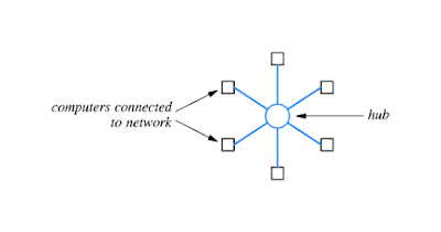
Star topology : A network uses a star topology if all computers attach to a central point.

Because a star-shaped network resembles the spokes of a wheel, the center of a star network is often called a hub. A typical hub consists of an electronic device that accepts data from a sending computer and delivers it to the appropriate destination.

In practice, star networks seldom have a symmetric shape in which the hub is located an equal distance from all computers. Instead, a hub often resides in a location separate from the computers attached to it.

Ring Topology :
A network that uses a ring topology arranges for computers to be connected in a closed loop. The name ring arises because one can imagine the computers and the cables connecting them arranged in a circle.

It is important to understand that the ring, like the star topology, refers to logical connections among computers, not physical orientation – the computers and connections in a ring network need not be arranged in a circle. Instead, the cable between a pair of computers in a ring network may follow a hallway or rise vertically from one floor of a building to another.

Bus Topology :A network that uses a bus topology usually consists of a single, long cable to which computers attach. Any computer attached to a bus can send a signal down the cable, and all computers receive the signal. Because all computers attached to the cable can sense an electrical signal, any computer can send data to any other computer. Of course, the computers attached to a bus network must coordinate to ensure that only one computer sends a signal at any time or chaos results.

Reference :
“Computer networks and Internets with Internet Applications (Third Edition), Douglas E. Comer, Prentice Hall”

Jan 26, 2008

Voice over IP (VoIP) Features

Because with VOIP you can make calls from anywhere you have access to a broadband connection, users can take their IP phones or ATA?s with them on trips and still have access to what is essentially their home phone.Some people use a softphone to access their VOIP service. A softphone is a specially developed software application that loads the VOIP service onto your desktop computer or laptop. Some even have an interface on the screen that looks like a traditional phone. These softphone applications allow you to place VOIP calls from your laptop; anywhere in the world you have access to a broadband connection.Most traditional phone companies charge you for extra features that are added to your account. With VOIP service providers these usually come as standard. Features such as:

1. Caller ID
2. Call Waiting
3. Call Transfer
4. Repeat Dialling
5. Return Call
6. Three-Way Dialling

Some VOIP service providers also offer advanced call filtering features. These additional features allow you to decide how calls to a specific number are handled by using caller ID information. They allow you to:

1. Forward the call to a particular number
2. Send the call directly to voicemail
3. Give the caller a busy signal
4. Play a "not-in-service" message

Many VOIP services also allow you to check your voicemail over the internet or attach messages to an e-mail that is sent to your computer or PDA. It?s best to check with VOIP phone system suppliers and service operators exactly what features they offer as package and service prices vary greatly.

There are many other cost saving benefits that arise from a streamlined VOIP phone system network. For the network administrators, a VOIP phone system means they only have one network to maintain instead of two. The portability of the phone system is also greatly simplified. This is because most VOIP phone systems can be configured using a web interface, which can be managed by the network administrator. The MAC (move, add, change) process is made much easier, and you will not have to call your system/service provider for every MAC you carry out. All this means lower ongoing costs for your company.

Another cost saving for companies who implement a VOIP system is, because multiple offices, no matter where they are in the world are seamlessly connected, they can share many of the features VOIP can offer, such as:

1. One single receptionist
2. Auto attendant facilities
3. Voice mail system

About the Author


Jason Morris is co-author, search engine optimization and marketing consultant of
Business Phone Systems Direct. Specialists in the supply and installation of business phone systems and accessories

VoIP (Voice over Internet Protocol)

VoIP (Voice over Internet Protocol) has promised much for a few years. But now it is fast becoming a viable option for many UK businesses and home workers. VoIP technology allows telephone calls to be made over the internet at a fraction of the cost compared with traditional telephony. If you operate a multiple site company, VoIP could bring you exceptional benefits.

How does it work?

The technology works by converting the (human) voice to data packets, transmitting it over the internet, indeed any data connection running IP and reconverting the packets into human voice once it has reached the destination.Normal voice is in an analogue format. This cannot be carried over data connections, so it is converted into digital sound packets so that it can be carried over the internet. This process is similar to internet technology where a modem is used to convert analogue data into digital and vice versa.

Benefits

You can speak to more than one person at a time (teleconference). There is also room for interactive video conferencing Excellent voice quality. In built firewall for security. This protects your business from telephone fraud. Cost effective as calls can be compressed. Saves money on cabling.